I became interested in the hardware side of Raspberry Pis a couple weeks ago.
We have this thing at work called “Hack Week”. Everyone spends a few days on things unrelated to their normal project work. The theme of this recent week was IoT and edge computing.
Everyone was given a Raspberry Pi Zero to hack with. Most people only used the Pi incidentally, including myself. There were a couple teams that came up with some interesting ideas using cameras. One team used a microphone.
Thinking about it for a week got me interested in doing more hardware stuff. I’ve thought about it before, but never seriously enough to take action. I’m more of a software guy.
I didn’t know what a breadboard was. The GPIO pins on the Raspberry Pi 4 that I use as a home server were a mystery to me. I’ve never soldered anything. I felt a bit embarrassed. It seems like I should have some experience with some of these things.
I ordered a Freenove Ultimate Starter Kit and I’m working through the tutorial. Here’s my journey through learning some basic electronics.
Lesson 0
The first thing I learned was that you can’t use the GPIO pins of the Raspberry Pi Zero without soldering. I spent an hour wondering why it wasn’t working when I held the header in the holes. At the time, I didn’t own a soldering iron.
I ordered Pi 4, since it has the header pre-soldered and soldering is still bit daunting. I also bought a soldering iron, although I haven’t used it yet. The later chapters of the tutorial mention soldering, so I’ll climb that hill when I get to it.
Another reason I ordered a Pi 4 is that the Pi Zero is slow. I spent half an hour git cloning the tutorial on the Zero. In retrospect I could have used --depth 1, which just now took about a minute. I installed pyenv, but gave up on installing Python 3.8 after a very long wait.
Lastly, I ordered a Pi 4 because I eventually want to run a private Wekan instance on it.
Lesson 1
For the first real lesson, I had to wire up a single LED and write some code to make it blink. To prepare for that, I had to learn what GPIO pins are, learn what a breadboard is, and hook up the Raspberry Pi to the GPIO extension board on the breadboard.
GPIO Pins
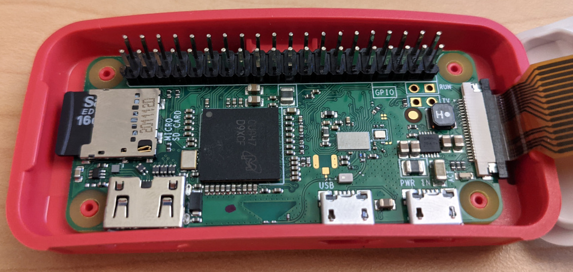
GPIO pins on the Raspberry Pi are the 40 conspicuous holes or metal pins that can be used to power or communicate with peripherals. Most of the pins can be controlled via software, others provide a route for power to travel through. Most of the pins are 3.3V, although there are some 5V pins. There are special pins for specific purposes that I hope to understand eventually.
Here’s a picture of my Pi Zero with a non-soldered header in the GPIO slots.
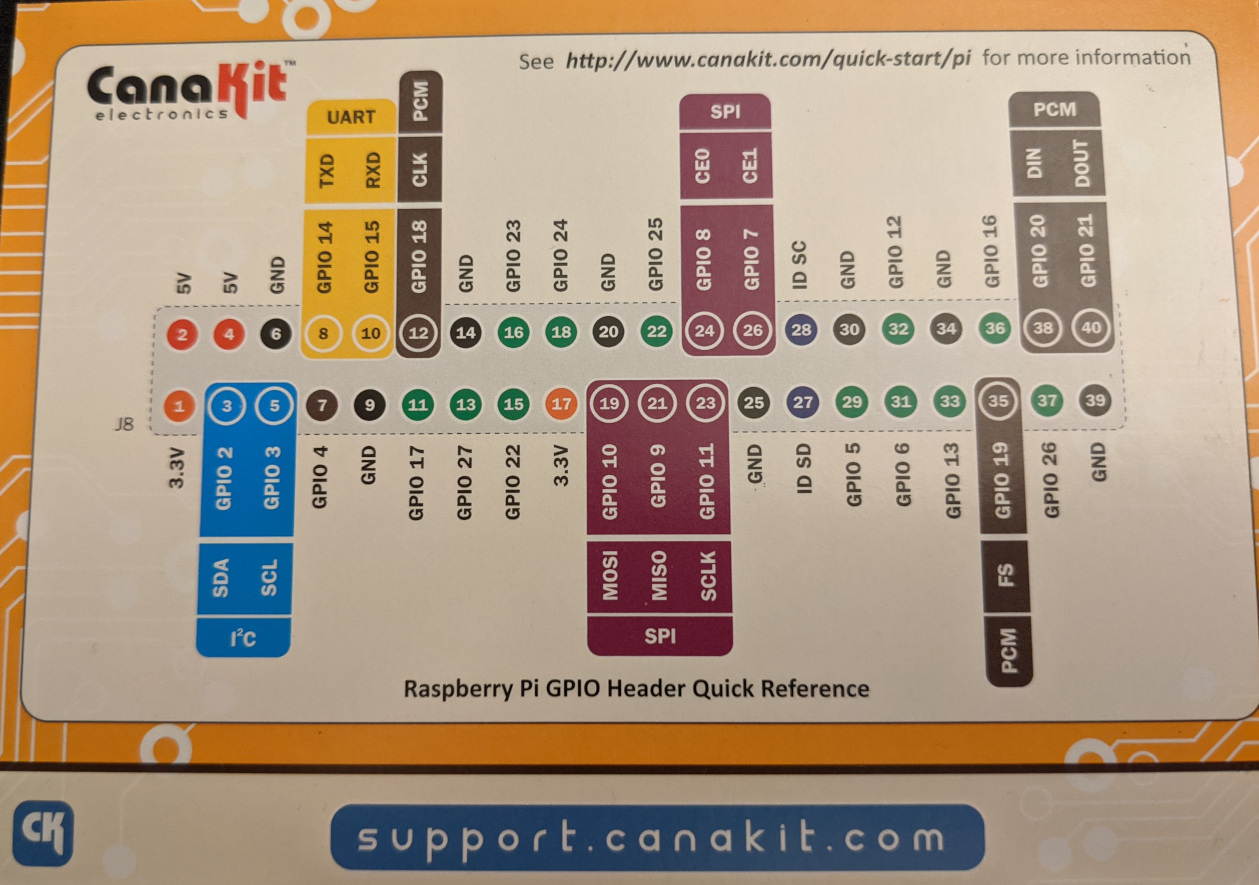
GPIO Pins have a few different numbering systems, which can be confusing. The code use the board numbering, but it takes some cross referencing, I use the CanaKit reference card. The numbers in the circle in the middle of the chart are the board numbers. The names of the pins are printed on the extension board.
Breadboard
A breadboard is a base for building electronic circuit prototypes. It’s design is to make it easy to play around, as opposed to soldering something effectively permanently.
It’s made of plastic with conductive metal bars inside. There are two central blocks of rows with 5 holes that are connected with metal. Two outer columns are connected all the way up and down the board, typically for grounding or power supply further down the board. The red lines in this image show which things are connected internally.
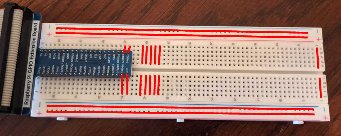
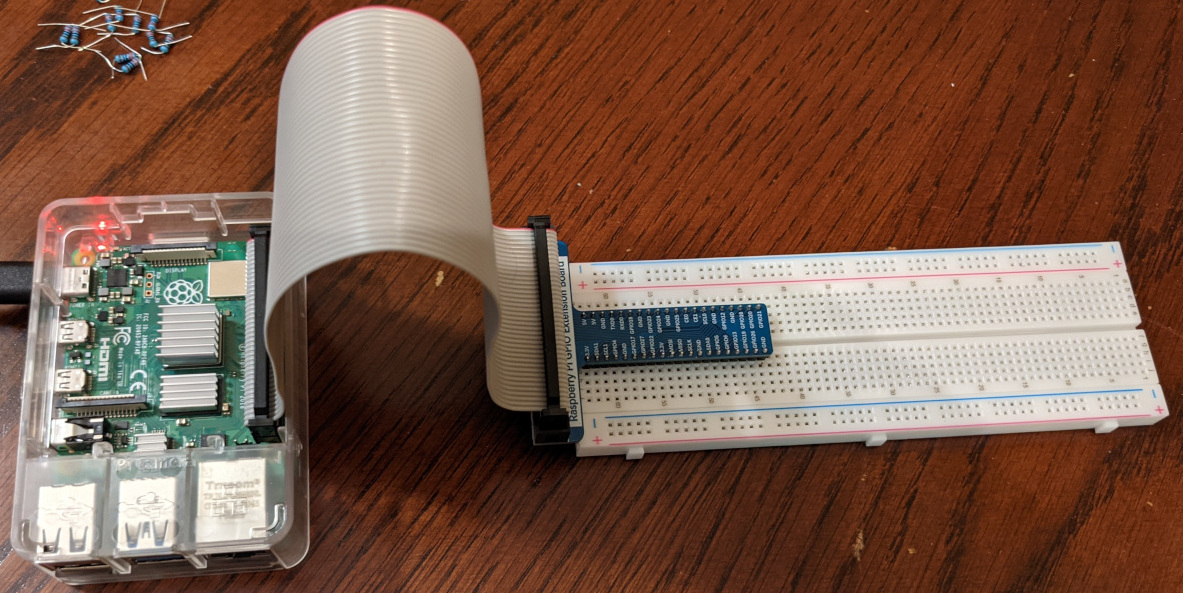
The blue board on the left of the breadboard is an extension board to connect the pins from the Raspberry Pi to the breadboard. This makes it simple to see which row is connected to which pin, since the extension board is labeled. Here’s what the Raspberry Pi looks like connected to the extension board.
Wiring up an LED
Now it’s time to wire up an LED and make it blink. The circuit needs to go from the GPIO 6 pin, through the LED, with a resistor to avoid breaking the LED, to ground. Here’s a picture.
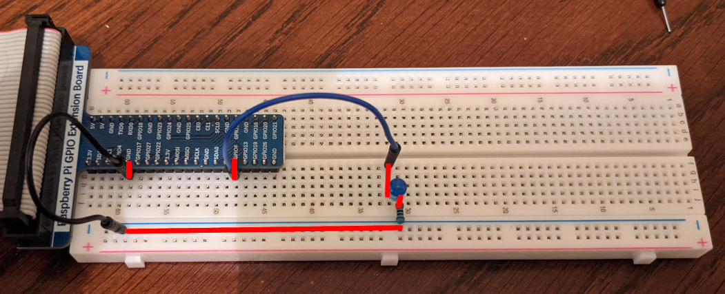
- GPIO6 pin is connected to the left end of the blue jumper cable.
- The right end of the blue jumper is connected to the positive (longer) end of the blue LED.
- The negative end of the blue LED is connected to a 220 ohm resistor.
- The resistor is connected to the bottom end of the black jumper.
- The top end of the black jumper is connected to a ground pin.
Here’s the code I use to make the LED blink on and off every half second.
import signal
from threading import Event

import RPi.GPIO as GPIO


class State:
    b_pin = 31

    event = Event()

    def __enter__(self):
        GPIO.setmode(GPIO.BOARD)
        GPIO.setup(self.b_pin, GPIO.OUT)
        GPIO.output(self.b_pin, GPIO.LOW)
        signal.signal(signal.SIGTERM, lambda s, f: self.event.set())
        signal.signal(signal.SIGINT, lambda s, f: self.event.set())
        return self

    def __exit__(self, _et, _ev, _t):
        GPIO.cleanup()

    def loop(self):
        while not self.event.is_set():
            GPIO.output(self.b_pin, GPIO.HIGH)
            self.event.wait(0.5)
            GPIO.output(self.b_pin, GPIO.LOW)
            self.event.wait(0.5)


if __name__ == '__main__':
    with State() as state:
        state.loop()
More LEDS
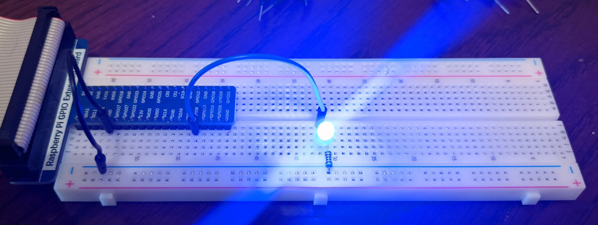
After that, I wanted to go a bit further, so I wired up four LEDS and coded them to toggle on and off in a wave pattern.
Here’s what it looks like in action.
Here’s the code.
import signal
from threading import Event

import RPi.GPIO as GPIO


class State:
    b_pin = 31
    g_pin = 33
    y_pin = 35
    r_pin = 37
    led_pins = [b_pin, g_pin, y_pin, r_pin]

    rotate_state = 0

    event = Event()

    def __enter__(self):
        GPIO.setmode(GPIO.BOARD)
        for pin in self.led_pins:
            GPIO.setup(pin, GPIO.OUT)
            GPIO.output(pin, GPIO.LOW)
        signal.signal(signal.SIGTERM, lambda s, f: self.event.set())
        signal.signal(signal.SIGINT, lambda s, f: self.event.set())
        return self

    def __exit__(self, _et, _ev, _t):
        GPIO.cleanup()

    def rotate_bgyr(self):
        pin = self.rotate_state % len(self.led_pins)
        output = GPIO.HIGH if self.rotate_state % (len(self.led_pins) * 2) < len(self.led_pins) else GPIO.LOW
        GPIO.output(self.led_pins[pin], output)
        self.rotate_state = self.rotate_state + 1

    def loop(self):
        while not self.event.is_set():
            self.rotate_bgyr()
            self.event.wait(0.5)


if __name__ == '__main__':
    with State() as state:
        state.loop()
Misc Lessons
The side columns of the breadboard aren’t connected to anything by default. I spent at least 15 minutes puzzled why I couldn’t use it to ground before I realized I had to connect it to a ground pin.
It’s ok to snip ends of a resistor. They came with 3cm wires on each end, which made them awkward to work with.
It doesn’t matter whether the resistor is before or after the LED, as long as the circuit has an appropriate resistance.
Amps = Volts / Ohms. With 3.3 volts and 220 ohms, we should have a 0.015 amps or 15mA of current to the LED. I feel like I don’t fully understand the electricity aspects. The Freenove tutorial says the maximum current for a Green or Blue LED is 10mA, but I haven’t seen issues if the 15mA calculation is correct. It also says the voltage range for a red LED is 1.9-2.2V, but 3.3V works as well.
I’d like to figure out how to install the RPi.GPIO on my laptop, so that my IDE can autocomplete stuff. I didn’t have any success, but I don’t know why.